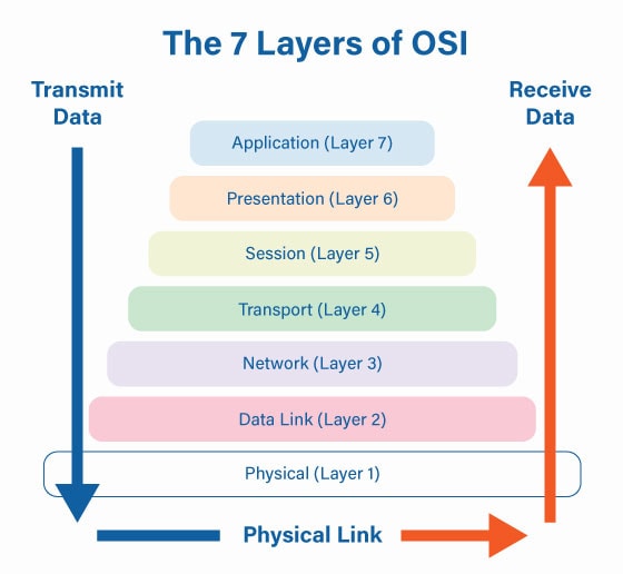
The Open Systems Interconnection (OSI) or OSI Model was invented as a representation to standardize communication between two computers. This networking model divides the networking process into 7 layers. Above all, these standards serve as a guide that helps vendors and developers create devices that interoperate with each other regardless of the brand.
All these 7 layers work collaboratively to transmit the data from one person to another across the globe. Nowadays, it is primarily used as a teaching tool for network architecture. This is an important part of CompTIA network+ certification.
What are the seven layers of the OSI model?
This OSI model can be seen as a common language for the computer networking framework. Each of the 7 layers of the OSI model contributes to the communication with the adjacent layers.
This seven-layer model is typically represented from top to bottom. These are the 7 Layers of the OSI Model:
1. Physical Layer
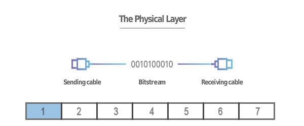
At Layer 1, the Physical layer of the OSI model is responsible for the ultimate transmission of digital data bits. This layer consists of all the physical equipment associated with data transfer. Layer 1 Ethernet cables, connectors such as NIC or network cards, and network Hubs and repeaters.
At the Physical layer, it’s important to know that data should be supported by the physical connection of your device. Layer 1 includes all the physical structure of the network:
- Physical Structure
- Coax
- Fiber
- Wireless
- Network Hubs
- Repeaters
2. Datalink Layer
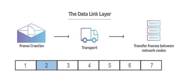
The Data link layer or layer 2 of the OSI model manages the physical addressing system such as MAC addresses. The data link layer handles data transfer between two devices on the SAME network.
Firstly, the data link layer takes packets from the network layer and breaks them into smaller pieces called frames. Like the network layer, the data link layer is also responsible for flow control and error control. Certainly, I want to emphasize that this is only for inter-network communications.
The data link layer has two sublayers: the LLC sublayer or logical link control and the MAC sublayer or media access control. In conclusion, layer 2 defines the format of data on the network by managing the physical addressing system of the network:
- Encapsulation
- Frame synchronization
- Logical link control (Error & Flow control)
- Media access control (MAC, Network Switch, Physical addressing, QoS, VLANs)
3. Network Layer
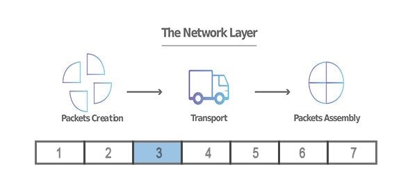
The network layer or layer 3 of the OSI model is responsible for facilitating data transfer between two different networks. A protocol that defines routing and addressing is considered to be a network layer, or Layer 3.
The network layer breaks up segments from the transport layer into smaller units, called packets. The network-layer devices responsible for routing these packets are common devices such as routers or Layer 3 switches.
In addition, the network layer devices also are in charge of determining the best physical path for the data to reach its destination; this is known as routing.
The protocols used in Layer 3 include:
- Internet Protocols IPv4/v6
- Internet Control Message Protocol (ICMP)
- Distance Vector Multicast Routing Protocol (DVMRP)
- Internet Group Management Protocol (IGMP)
- Address Resolution Protocol (ARP)
- Internet Protocol Security (IPsec)
- Routing Information Protocol (RIP)
4. Transport Layer
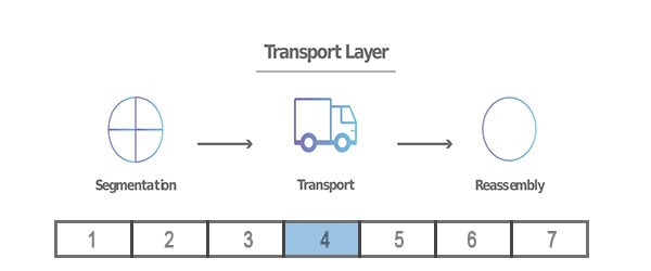
The transport layer or Layer 4 of the OSI model is in charge of the communication between the two devices in a network. Layer 4 Transport examples include SPX, TCP, and UDP. This includes data flow controls and providing error-checking mechanisms to the already established communication.
The flow control defines the optimal speed of transmission. In other words, it assures that the receiving end device can handle the transmission. In addition, the transport layer ensures that the data received is complete.
Layer 4 works by taking the data from the session layer and dividing it up into smaller pieces called segments. This dividing process is completed before sending it to the network layer. Consequently, the transport layer on the receiving end of the message reassembles the divided segments.
* Data in the Transport Layer is called as Segments.
5. Session Layer
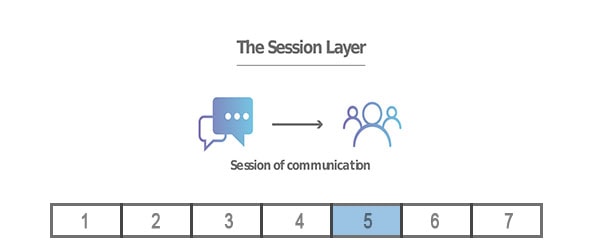
The session layer or Layer 5 of the OSI model is responsible for creating and closing the communication between the two devices. This is known as a Session. Layer 5 maintains the session open until the transfer completes subsequently closing afterward.
Its services include authentication and reconnection after an interruption. In addition, layer 5 synchronizes data transfer with checkpoints. To clarify, here is an example of layer 5.
Firstly, Let’s say that we are transferring a 100-megabyte file. As a result, the session layer sees the file and sets a checkpoint every 5 megabytes. This is very important during transferring failures. Because it allows the transmission to resume from the last checkpoint. Consequently, saving network processing power.
Layer 5 Session examples include NFS, NetBios names, RPC, SQL.
6. Presentation Layer
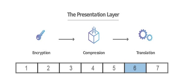
The presentation layer or layer 6 is in charge of translating or formatting the data for the application layer. In other words, the presentation layer makes the data presentable for layer 7.
Secondly, the presentation layer is the layer that handles the encryption and decryption of data for the application layer.
Finally, layer 6 is also responsible for the compression of data received from the application layer. This is done before delivering it to layer 5. Therefore, improving the speed and efficiency of communication during the data transferring process.
Layer 6 Presentation examples include encryption, ASCII, EBCDIC, TIFF, GIF, JPEG, MPEG, MIDI.
7. Application Layer
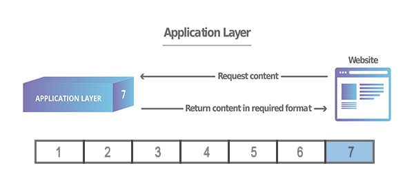
Layer 7 or the application layer is the layer that directly interacts with data from the user. This layer includes software applications like web browsers and email clients. Layer 7 Applications include web browsers and other internet-connected apps, such as Outlook and Skype.
To clarify, it should be made clear that client software applications are not part of the application layer. On the contrary, the application layer is responsible only for data protocols. Consequently, the software relies on this layer to present meaningful data to the user.
Application layer protocols include the Hypertext Transfer Protocol or HTTP and Simple Mail Transfer Protocol or SMTP.
The Bottom Line
In conclusion, the OSI reference model’s main purpose is to standardize how computers communicate with one another over a network. This seven-layer model is typically represented from top to bottom. In order from seven to one, the layers are as follows: application, presentation, session, transport, network, data link, and physical layer.

Victor Hugo Solis
Master’s Degree in Information Security, a Bachelor’s Degree in Database Administration, and experience as a WordPress Web Designer & Developer.